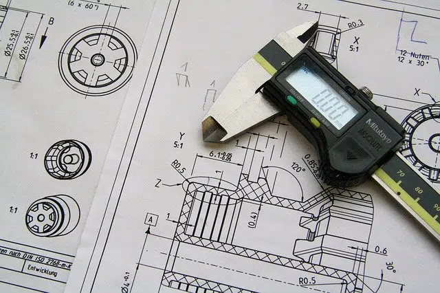
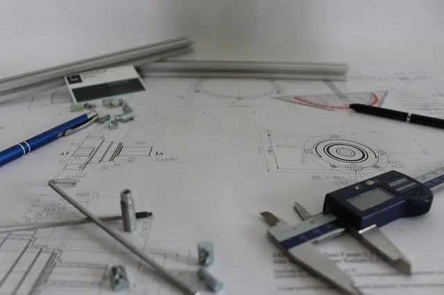
A mechanical drawing allows you to represent a machine, or part of it, through a graphic.
To understand what a mechanical drawing is, we must first consider each term that makes up the expression separately. A drawing is a line or delineation that allows a figure to be represented. The mechanical , for its part, can be linked to a machine, a device or a mechanism.
A mechanical drawing , therefore, is a graphic representation of machinery , part of it or its parts . These are plans or diagrams that show the layout or operation of these devices.
Mechanical drawings are part of the set of technical drawings : those that, by representing an object, provide data that enables its design, manufacturing, operation and/or maintenance. Electrical drawings and architectural drawings are also considered technical drawings.
Origin of mechanical drawing
The importance of drawing to transmit ideas through graphics and lines has been considerable over many millennia. Let us not forget that long before humans invented and developed writing systems, they relied solely on art to express themselves and record their ideas and experiences.
When writing finally appeared, drawing became an activity of certain specialists, both artists and people with needs that the written language could not cover, as is the case today of engineers and designers who need to prepare plans, sketches and sketches for your work activities.
Its usefulness
Like the rest of the technical drawings, mechanical drawings must show those details that are required to execute a project. They generally use different symbols to represent cuts, lines and other elements. Standardization allows the same symbols to be used globally, favoring understanding among specialists.
The use of symbols has another objective in addition to making it possible for people from all over the world to read a plan: to simplify the drawing and minimize the probability of error. If engineers did not have at their disposal a series of conventions to easily represent certain concepts, they would be forced to design devices and parts with the greatest possible degree of realism, and that would entail very arduous work, which would not always be accurately reflected. total precision the less obvious characteristics of the products.
Mechanical drawings usually appeal to symbols.
Standardization and symbology of mechanical drawing
According to the International Organization for Standardization (whose name in English is the Organization for Standardization and its acronym, ISO ), two representation systems are currently used, the American and the European, also known as the third quadrant and the first quadrant , respectively. Trends indicate that in the future American will be used in almost all cases.
With respect to the symbology of each one, it is important to note that the user must know in advance which one the mechanical drawing corresponds to in order to understand it correctly, since the same symbol can mean different things in one and another. For example:
* for ISO(E), the European representation system, P , Q and R are used to symbolize the front, top and side views, respectively;
* The American system, ISO(A), on the other hand, uses P , Q and R to represent the top, front and side views, respectively.
Use of computing resources
It should be noted that a mechanical drawing can be developed by hand on a flat surface (such as paper) or carried out virtually with the help of a computer program ( software ). In this way, 3D representations can be generated and different perspectives obtained.
An example of a mechanical drawing is the graph that shows all the parts of an engine . Thanks to this representation you can understand how the different gears are formed and how the whole works.