An electrical drawing makes it possible to represent an electrical installation.
The first step we are going to take is to know the etymological origin of the two words that give shape to the term electrical drawing that concerns us:
-Drawing comes from French, exactly from the verb “déboissier”, which can be translated as “draw”.
-Electrical, for its part, derives from Greek as it is the result of the sum of two clearly differentiated components of that language: the noun “élektron”, which means “amber”, and the suffix “-ikos”, which is used to indicate “relative to”. This term, it should be stated, was coined by the British physicist William Gilbert (1544 – 1603).
A drawing is a line made on a surface. It is usually an image or representation of something. Electric , for its part, is that linked to electricity : the force manifested by the rejection or attraction between charged particles, and the form of energy that is based on said force.
What is an electrical drawing
The diagram that is made to represent an electrical installation is called an electrical drawing . These representations use symbols to refer to the switches, circuit lines and the rest of the components of this type of installation.
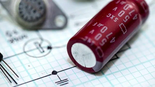
There are many symbols that appear in a drawing of this type and that must be known. Specifically, there are two types of them: electronic ones, such as resistors and capacitors, and electrical ones. Among the latter are the light bulb, the motor, the voltmeter, the battery, the switch...
Among the components that should not be missing in any electrical drawing are the meter box, the switches, the main board, the socket, the circuit line, the lamp outlets or the connections, for example.
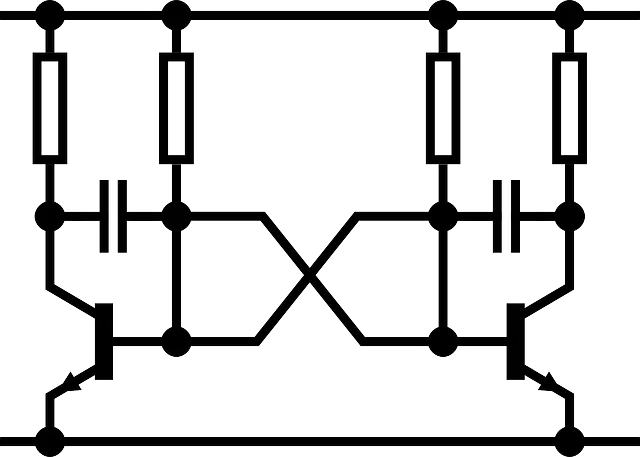
Electrical drawings use symbols.
Technical graphic representation
Electrical drawings are part of the set of technical drawings , which are graphic representations whose purpose is to provide useful information to analyze, design, build and/or maintain some type of installation, infrastructure or work. Architectural drawing, electronic drawing and mechanical drawing are other technical drawings.
When making an electrical drawing or any other technical drawing, it must be taken into account that a wide variety of types of lines must be used, among which guide lines, symmetry lines, hidden lines, and breaking lines stand out. , the center one or the dimension ones, for example.
Usefulness of electrical drawing
An electrical drawing can be useful for diagramming or remodeling the electrical installation of a house, business or industry. It is also linked to motors and other electrical devices. Its preparation must be developed by an electrical engineer since the author must have the necessary technical knowledge to make the representation in question.
Take the case of the construction of a house. In addition to the architect's work regarding the material structure of the construction (walls, roof, etc.), a specialist will be needed to develop the electrical drawing of the facilities to define where there will be outlets, where the electrical outlets will pass. cables and other details related specifically to electricity.